- Home
- Products
- Articles
- 4 Axis Robot Arm
- A Stepper Motor Driven Ferris Wheel (Version 3 Compiler required)
- An Update on Keith Cameron's Lift
- Automatic Tram Layout
- Bug in Increment Word Instruction
- Compiler Version Releases
- Industrial Arc Welding Robot
- MotorVating the Speed Play Robot
- Reproducing the Electronic Set Models
- Sensor Expansion Port Pinout Diagram
- Sheet 1 - Hardware from NZ 240 volt wall socket to...
- Sheet 3 Meccano Car model controlled by the MotorVator and Director.
- Sheet 2 - Hardware from Motor(s) to MotorVator®.
- User Input Options
- Version 3 Manual Released
- 16/32 Bit Maths Routines
- Build Your Own Photo Sensor
- Controlling Stepper Motors
- Magnetic reed switch as a non contact sensor
- MeccCompiler III Tutorial
- More Inputs and/or Motors: Port Replication
- More Inputs: the Sensor Expansion Port
- Square Root Function
- Tutorial: Rev Counter
- Use of the opto switch or opto interrupter as a ro...
- FAQ
Sheet 1 - Hardware from NZ 240 volt wall socket to...
MotorVator® Group For Absolute Dummies (MGFAD)
Following discussion at the MWT Meccano Club April 2005 meeting, the following MotorVator® owners decided to provide mutual support to achieve the required action from their units. Bruce Geange, John Jordan, Bob Prescott, Lou Nichols, Simon Moody, Daryl Anderson, Robin Rye, and Bruce Neilson. The group will take their discussion at the lowest possible level to ensure correct actions. Dummies  and proud of it!!
Sheet 1 - Hardware from NZ 240 volt wall socket to MotorVator®.
Version 1.0, 17 April 2005.
1 - Action – From a Dick Smith Electronic store, purchase at least one (maximum three) M9917 AC International Adaptor (alias transformer) NZ$39.95.
Explanation – This transformer unit provides regulated power, is rated at 1.25 amps, choice of 3, 4.5, 6, 7.5, 9, 10.5 and 12 volts. There are three “Power Input Sockets†on the end of the MotorVator® unit, each of which may eventually need a M9917 transformer.
Picture – 6415 Transformer in packet, 6416 Transformer mains pins.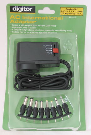
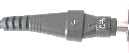
2 – Action – Included with the transformer is a strip of eight roundish plugs with two pins. The second largest round socket plug is plugged into the two hole socket at the end of the transformer cable. ABSOLUTE MUST. The word “CEN†(alias “Centre) on the round plug MUST line up with the “-“ (negative) symbol on the transformer cable socket.
Explanation – The centre hole of the round socket plug must be Negative as required by page 12 and 16 of the ring binder Manual supplied with the MotorVator® boxed set.
Picture – 6420 Second round socket plug from strip. 6417 Transformer two pin socket, 6419 Centre and Negative round socket plug.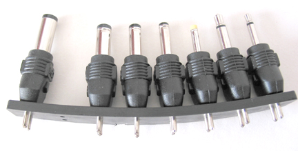

2A – Action – DOUBLE CHECK ACTION 2 or you will burn out your MotorVator®.
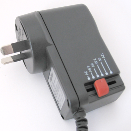
3 – Action – Set the voltage to 9 volts by moving the red slider on the side of the transformer.
Explanation – The minimum voltage to start the MotorVator® is 5 volts into the Power Input Sockets AB (page 17 of ring binder Manual).
Picture – 6416 Transformer and outwards voltage shown set at 6 volts (but please set to 9V).
4 – Action - Connect the “Director Cable†(has two plugs each with 15 pins) to the socket (alias port) on the Director (Box with two toggle levers and two buttons shown on page 38 of the ring bound Manual) and to the socket (alias MotorVator® Sensor Expansion Port) on the MotorVator® (item 18 on page 11 of the ring bond Manual). Secure by screwing the finger screws into their threaded sockets.
Explanation – This cable allows the Director and MotorVator® to send commands to each other.
Picture – 6424 Director cable 15 pin.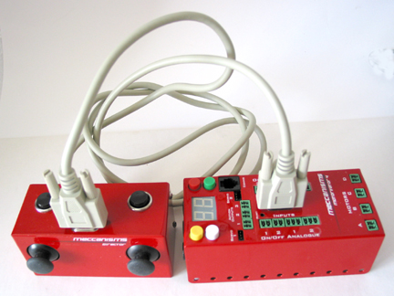
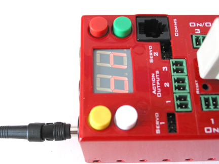
4 – Action – Check that the 240 volt power wall switch is OFF. Plug the transformer into the 240 volt wall socket (or 240 volt multibox), and then push the cable round plug into the Power Input Socket AB of your MotorVator®. Turn the 240 volt power ON at the wall. The MotorVator® will play a short fanfare and the two character LCD display will light up and display “onâ€.
Explanation – This procedure is laid out on page 12 and 13 of the ring bound Manual. You now have electricity from the wall socket into the MotorVator®.
Picture – 6418 MotorVator®, round socket plug, and LCD screen.
5 - Additional Explanation – Your MotorVator® now has sufficient volts and amps to drive two or more Meccanisms geared motors or equivalents (see Sheet 2). As stated in Action 1 above, eventually you may need two more Dick Smith M9917 transformers to plug into MotorVator® Power Input Sockets CD and Action to drive another two motors, and Action Outputs and Servo outputs. See pages 19 and 20 of the ring bound Manual.
Note that The MotorVator supports "split voltages" to allow you to operate motors of different voltages. In MOST cases, you can run all the outputs (i.e. 4 motors, 2 Servo Motors, 3 Action ports) from a single Power Input into Power Input Socket AB.
6 – Action – Turning off the MotorVator®. The instructions are on page 14 of the ring bound Manual and are repeated below.
Press the MotorVator® Red Off button to stop any program running. Again press and hold down the Red Off button for at least 2 seconds, a tune will play and the two character LCD display will go out. The transformer can then be unplugged from both MotorVator® and the 240 volt socket.
Comments, corrections and feedback to Bruce Neilson.