|
Getting User Input into your MotorVator
Many of the models that we build are self-sufficient: they take input
from sensors within the model and make decisions accordingly.
Some models however need to interact with Humans. An example is my
TicTaeToe Player.
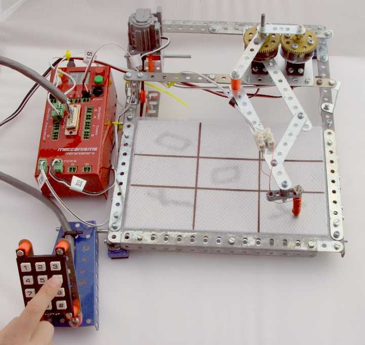
The MotorVator software is programmed to decide which moves to make, and draw the
symbol on the board, but [obviously] needs to be told about my moves.
Here are three options for getting User Input:
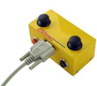
The simplest way is to use the Meccanisms Director to input my moves.
The READ BUTTON command lets you check whether any of the Director Buttons
are being pressed. So we use one button to cycle the Square_Number Up,
another to Cycle it Down, and a third to "Lock In" our move.
In MeccCode II:
......
' Get Move Routine
					do

					    If Joystick1Button2 = 1 then        ' Left Front Button Goes Up

					        Increment Square_Number

					        If Square_Number = 10 then        ' Wrap from 9 to 1

					            Square_Number = 1

					        End if

					    End if
					    If Joystick2Button2 = 1 then        ' Right front  Button Goes Down

					        Decrement Square_Number

					        If Square_Number = 0 then

					            Square_Number = 9    ' Wrap from 1 to 9

					        End if

					    End if

					Until (Joystick1Button1 = 1)    ' keep looking at the director buttons

					                                                 until the "Lock In Move" button is pressed
.....
The Meccanisms Director is easy to implement, but you might prefer to
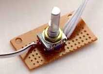
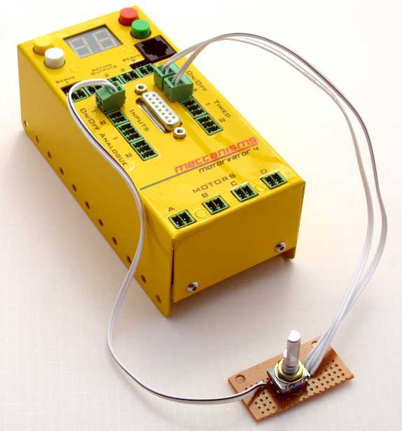
not need to have it attached. Next option is to use a rotary encoder. This
looks like a volume knob, but can rotate either way and can be pressed.
Some rotary encoders can tell you at which angle they are set: this one
simply tells you how many 'clicks' it has turned, and in which direction.
We've left the knob off so you can see the rotary encode itself. The piece
of matrix board is drilled to match Meccano spacing for mounting in a
frame.
So we set it up to Increment the Square_number when turned Clockwise,
Decrement when turned the Counter-Clockwise, and "lock in" the move when
pressed.
This rotary encoder has two "channels" that give pulses as
the knob is turned. The timing diagram looks like this (the dotted lines
show the position where the knob "clicks" and stays put"):
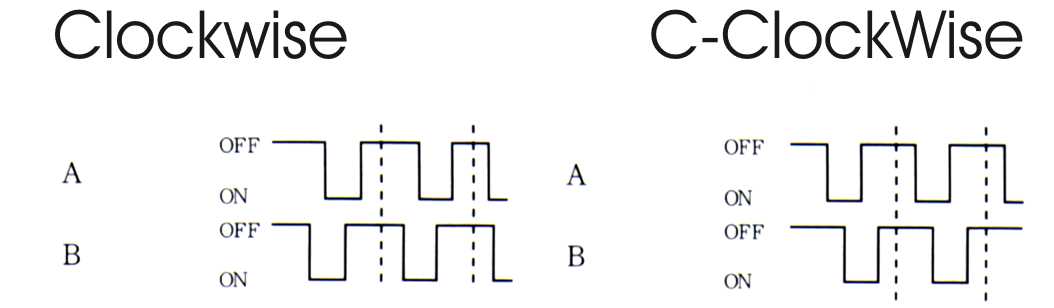
So to work out which way the knob has turned, we do the following:
1. When the level of channel A (Digital Input 3) changes, we firstly
check to see if it has changed to LOW. If not then we ignore the change,
because it is the "Falling edge" that we need to check. Note
that we use an EVENT to make sure that we can immediately catch when
Channel A changes.
2. If it is a falling edge, then we check the level of Channel B (Digital
Input 4). From the diagram we can see that if Channel B is LOW at the
point where Channel 1 goes from High to Low (the "falling edge")
then we are turning Clockwise, otherwise we are turning
CounterClockWise.
So the Rotary Encoder takes up three of our Digital Inputs: 1 for
ChannelA, 1 for ChannelB and 1 for the "Lock In Move" press. If
we didn't need to check for direction then we could get away without
Channel B. You might say use a Ratchet Wheel to limit the possible
direction of rotation to Clockwise only.
In MeccCodeII, it will something like this:
SetEvent CheckEncoder, OnOff3Event ; the CheckEncoder Routine will run with any change of OnOff3 Event
......
' Get Move Section
do
Square_Number = Square_Number + Ce_CW
Ce_CW = 0 ; clear any ClockWise Pulses, now that we' ve used them
If Square_Number = 10 Then
Square_Number = 1 ; and cycle around from 9 to 1 if required
End If
Square_Number = Square_Number - Ce_CCW
Ce_CW = 0 ; clear any CounterClockWise Pulses, now that weve used them
If Square_Number = 0 Then
Square_Number = 9 ; and cycle around from 1 to 9 if required
End If
Until ReadOnOff(1) = 1 ; do until the Lock In Move Button is pressed
; Now we have a move in Square_Number
....
.....
Declare EventHandler CheckEncoder()
If ReadOnOff(3) <> 0 Then ; we are only interested if the Channel A (OnOff3) has gone to 1
If ReadOnOff(4) = 1 Then ; If Channel B is 1, then
Ce_CCW = Ce_CCW + 1 ; Counter Clockwise turn
Else
Ce_CW = Ce_CW + 1 ; Clockwise Turn
Endif
Endif
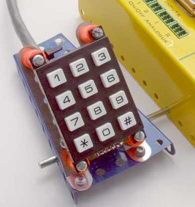
The rotary encoder is compact, but not that intuitive for kids. So a
better alternative is a keypad that maps to the tictactoe board.
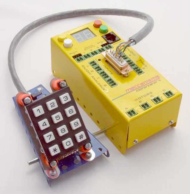
The keypad is about $US5, from Jaycar (www.jaycar.com.au catalogue
SP0770). It is wired as a simple 4 rows by 3 columns matrix. As purchased,
there is no logic built in - it is a simple collection of switches.
By wiring it as above, we can use Analog Inputs 3 to 6 to determine
when a key is pressed.
We connect each column to ground via a different value resistor. The
values of the resistors used are not critical - we chose 19K, 47K and 82K
to give a reasonable separation.
Now the cunning part:
When no key is pressed, all of the Analog Inputs
will have a reading of 250+.
When a key is pressed, one of the
Analog ports will be connected to ground via one of the resistors:
All the keys from the same column (e.g. 1, 4, 7 and *) will give the
same reading.
Which key it is depends on which Analog Port has this reading.
In the Diagram above,
- Keys 1, 2 and 3 are connected to analogue Input 4.
- Keys 4, 5 and 6 are connected to analogue Input 3.
- Keys 7, 8 and 9 are connected to analogue Input 6.
- Keys *, 0 and # are connected to analogue Input 5.
So if we get a reading of 90 from Analog Input 6, we know that the key
pressed is an 8 (middle column, row 3).
(This system has the advantage of not requiring debouncing, but can't cope
with more than one key pressed at a time. (Debouncing can be needed when
you connect a simple press-switch to an input. As the switch closes it
often generates a momentary contact, then goes open before settling down
to closed. Therefore to make the detection reliable it is normal to check
the status more than once before confirming that the switch is indeed
closed. There is more to debouncing that this, but we will leave that for
another day  ). ).
In MeccCode II, this routine will look like
Declare Function Keypad () Returns Byte

					Keypress = 0

					Keyadc = ReadAnalog(4)
					if KeyAdc < 80 then

					    Return 1

					end if

					if KeyAdc < 120 then

					    Return 2

					end if

					If keyAdc <180 then

					    Return 3

					end if
					KeyAdc = ReadAnalog (3)<br>

					if KeyAdc < 80 then

					    Return 4

					end if

					if KeyAdc < 120 then

					    Return 5

					end if

					If keyAdc <180 then

					    Return 6

					end if
					Keyadc = ReadAnalog(6)

					if KeyAdc < 80 then

					    Return 7

					end if

					if KeyAdc < 120 then

					    Return 8

					end if

					If keyAdc <180 then

					    Return 9

					end if
					return 0

					End Function
|