- Home
- Products
- Articles
- 4 Axis Robot Arm
- A Stepper Motor Driven Ferris Wheel (Version 3 Compiler required)
- An Update on Keith Cameron's Lift
- Automatic Tram Layout
- Bug in Increment Word Instruction
- Compiler Version Releases
- Industrial Arc Welding Robot
- MotorVating the Speed Play Robot
- Reproducing the Electronic Set Models
- Sensor Expansion Port Pinout Diagram
- Sheet 1 - Hardware from NZ 240 volt wall socket to...
- Sheet 3 Meccano Car model controlled by the MotorVator and Director.
- Sheet 2 - Hardware from Motor(s) to MotorVator®.
- User Input Options
- Version 3 Manual Released
- 16/32 Bit Maths Routines
- Build Your Own Photo Sensor
- Controlling Stepper Motors
- Magnetic reed switch as a non contact sensor
- MeccCompiler III Tutorial
- More Inputs and/or Motors: Port Replication
- More Inputs: the Sensor Expansion Port
- Square Root Function
- Tutorial: Rev Counter
- Use of the opto switch or opto interrupter as a ro...
- FAQ
Use of the opto switch or opto interrupter as a ro...
The opto switch or interrupter is a small U shaped black plastic package with a infra red LED on one side of the U and a light sensitive transistor on the other. This is shown in figure 1.
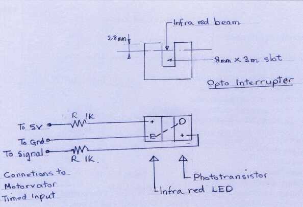
This figure also shows a circuit for connection to the Motorvator Timed Input Port. The LED side of the interrupter is sometimes marked with an E and a +. The + should be connected to the +5V on the Motorvator via a current limiting resistor. These opto switches vary but I have found a 1K resistor usually works well. The E should be connected to the Gnd on the Motorvator timed input and also to the diagonally opposite pin on the opto switch which may be marked with an D. The other pin on the transistor side of the opto switch is connected to the signal pin on the Timed Input of the Motorvator. (See Motorvator Manual) via a current limiting resistor. Again I have found a 1k resistor works well on the various opto switches I have tried.
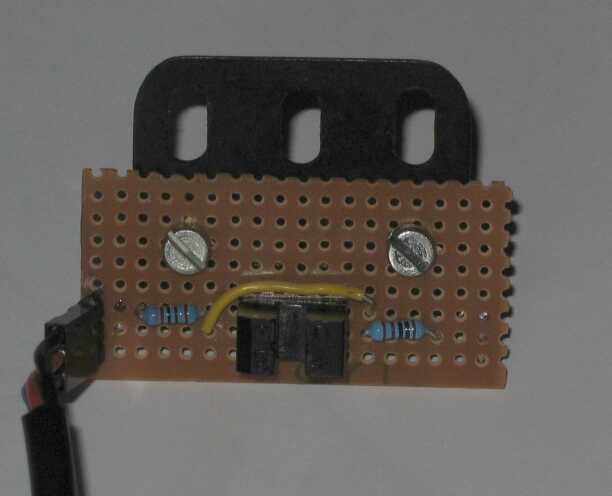
Figure 2 shows the components assembled on a small piece of copper strip board which is drilled with Meccano compatible holes for easy attachment to the model. I have taken the connections to three small pins which can connect to a servo type plug and hence to a Motorvator plug. Take care at the Motorvator plug that the connections are as described above and shown in figure 1. The Motorvator sends a small current through the LED side of the unit which transmits a tiny infra red beam to the transistor side of the unit. If this beam is interrupted the signal on the signal pin will change and a count will be made. A segment of code is shown below (Code)which shows how these signals can be used to control the motor.
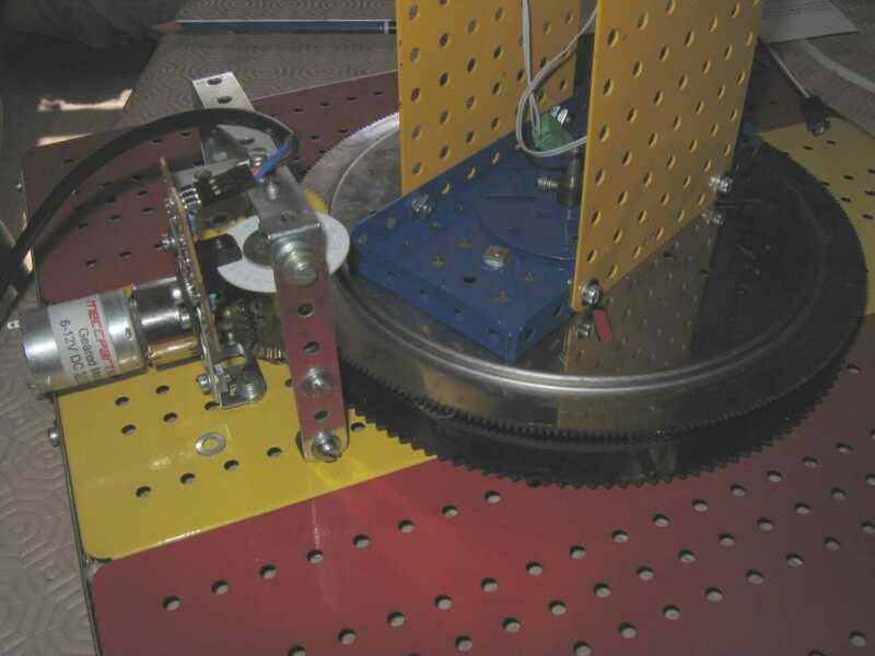
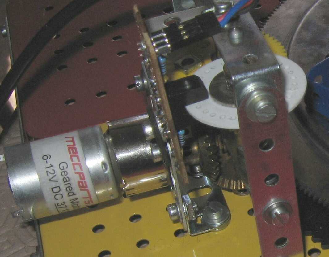
Figure 3 shows the rotation counter incorporated into a model. In this case the Motorvator Rotation sensor plastic wheel has been drilled with 2mm holes to act as the interrupter but a Meccano bush wheel or sprocket could also be used depending on the resolution required. The resolution may also be increased by gearing up the counter say 3 to 1. Experiment to obtain the best arrangement.