- Home
- Products
- Articles
- 4 Axis Robot Arm
- A Stepper Motor Driven Ferris Wheel (Version 3 Compiler required)
- An Update on Keith Cameron's Lift
- Automatic Tram Layout
- Bug in Increment Word Instruction
- Compiler Version Releases
- Industrial Arc Welding Robot
- MotorVating the Speed Play Robot
- Reproducing the Electronic Set Models
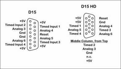
- Sensor Expansion Port Pinout Diagram
- Sheet 1 - Hardware from NZ 240 volt wall socket to...
- Sheet 3 Meccano Car model controlled by the MotorVator and Director.
- Sheet 2 - Hardware from Motor(s) to MotorVator®.
- User Input Options
- Version 3 Manual Released
- 16/32 Bit Maths Routines
- Build Your Own Photo Sensor
- Controlling Stepper Motors
- Magnetic reed switch as a non contact sensor
- MeccCompiler III Tutorial
- More Inputs and/or Motors: Port Replication
- More Inputs: the Sensor Expansion Port
- Square Root Function
- Tutorial: Rev Counter
- Use of the opto switch or opto interrupter as a ro...
- FAQ
Bringing Models to Life