- Home
- Products
- Articles
- 4 Axis Robot Arm
- A Stepper Motor Driven Ferris Wheel (Version 3 Compiler required)
- An Update on Keith Cameron's Lift
- Automatic Tram Layout
- Bug in Increment Word Instruction
- Compiler Version Releases
- Industrial Arc Welding Robot
- MotorVating the Speed Play Robot
- Reproducing the Electronic Set Models
- Sensor Expansion Port Pinout Diagram
- Sheet 1 - Hardware from NZ 240 volt wall socket to...
- Sheet 3 Meccano Car model controlled by the MotorVator and Director.
- Sheet 2 - Hardware from Motor(s) to MotorVator®.
- User Input Options
- Version 3 Manual Released
- 16/32 Bit Maths Routines
- Build Your Own Photo Sensor
- Controlling Stepper Motors
- Magnetic reed switch as a non contact sensor
- MeccCompiler III Tutorial
- More Inputs and/or Motors: Port Replication
- More Inputs: the Sensor Expansion Port
- Square Root Function
- Tutorial: Rev Counter
- Use of the opto switch or opto interrupter as a ro...
- FAQ
Sheet 2 - Hardware from Motor(s) to MotorVator®.
MotorVator® Group For Absolute Dummies (MGFAD).
Dummies  and proud of it!!
Sheet 2 - Hardware from Motor(s) to MotorVator®. Version 1.0, 1 May 2005.
1 - Action – From Andrew Wells at www.meccparts.com purchase two 296 rpm geared Motors NZ$30 plus GST plus freight each.
Explanation – Because the MotorVator® group is working at the level of absolute dummies, this initial purchase takes out the guesswork as to what sort of Motors do you require. These Motors come with a four hole by three hole steel plate with lots of predrilled Meccano bolt size holes and three sets of attaching screw holes, and two 2mm attaching screws. The steel plate will allow you to bolt the Motor anywhere to your model
Picture – 6422 Motor, steel plate and screws.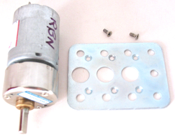
2 – Action – Insert the shaft of the motor through one of the three large holes and line up the 2mm screw holes on the steel plate with the 2mm screw holes in the end of the Motor casing. Insert and screw in the 2mm screws and tighten reasonably.
Explanation - The holes are a tight fit and you will need a small Phillips screwdriver to fit into the head of the screw and a bit of grease to lubricate the thread.
Picture - 6421 Motor assembled.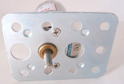
3 – Action –From Dick Smith Electronics store, buy (a) Wire, W4010 Flexible Light Duty Hookup Wire 0.12mm NZ$5.33 which is a bundle of twelve different coloured, multi-stranded, 1 amp rated, insulated (plastic covered), each two metres long. (b) Optional heatshrink tube W4401 3mm NZ$6.48.
Explanation – Each wire specification will eliminate any problems of getting electricity from the MotorVator® to the Motor. Heatshrink tubing covers all bare wire and Motor wiring tabs to prevent any possibility of short circuits across to metal Meccano.
4 – Action - 95% Method - Fold one of your two metre lengths of hook-up wire in half and cut it half to one metre lengths. Remove 20mm of insulation from the end of one of your one metre lengths of wire and twist the collection of exposed multi-strand wires into one bundle. Thread onto the wire 20mm of heatshrink tubing. Thread the twisted bundle of wire through the hole in one tab of the Motor and bend the wire into a U shape and twist the end of the wires around the base of the wires to make a secure loop. Slide the heatshrink tubing over the bare wire and Motor tab for insulation purposes and heat the tubing (hot air gun, above the flame of a cigarette lighter, or stroke gently with a hot soldering iron) to shrink. Repeat total action with another one metre wire so that the Motor has a wire on each of the two tabs. Repeat for all motors
OR 100% Method – Also buy some (c) Rosin core solder, NZ$10. (d) Purchase any other necessary soldering tools, and read and practice the basic methods of best soldering practice as set out at the Internet site http://tools.aubuchonhardware.com/do_ ... rojects/how_to_solder.asp .
Fold one of your two metre lengths of hook-up wire in half and cut it in half to one metre lengths. Remove 5mm of insulation from the end of one of your one metre lengths of wire, tin (alias cover with molten solder) the collection of exposed multi-strand wires into one bundle. Thread onto the wire 20mm of heatshrink tubing. Thread the tinned bundle of wire through the hole in one tab of the Motor and bend slightly so that the wire sits snugly against the tab. Solder the bundled wire to the tab. Slide the heatshrink tubing over the bare wire and Motor tab for insulation purposes and heat the tubing (hot air gun, above the flame of a cigarette lighter, or stroke gently with a hot soldering iron) to shrink. Repeat total action with another one metre wire so that the Motor has a wire on each of the two tabs. Repeat for all motors required.
Explanation – A solder join is the strongest join (and you will have to learn how to solder sooner rather than later .
Picture – 6443 Wire on motor.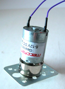
5 – Action – Each motor will require a two hole plug (supplied in the MotorVator® packing box) at the other end of the one metre wires. Remove 10mm of insulation from the end of one of the metre wires, twist the bare multi-strand wires into a bundle, fold the bundle in half and insert the bare wire into the hole in the plug so that no bare wire is exposed and screw down the holding screw. Repeat for the other wire. Repeat for all motors required.
Explanation – Your Motors are now ready to plug into your MotorVator®. Extra plugs are available from www.meccparts.com as PHNX2 at $1.50 plus GST plus freight
Picture – 6444 Wire in Plug.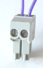
6 – Action – Refer to Sheet 1 and make sure that your MotorVator® is “onâ€. Lay the first Motor (now labelled ‘A’) on it’s side so that the Motor shaft cannot get tangled with anything and is totally free. Insert the ‘A’ Motor plug into the socket labelled “Motors A†on the MotorVator®. Nothing will happen! Refer page 14 in the ring binder Manual. The instructions are as follows:
6a - MotorVator® displays ‘on’.
6b – Press Yellow up Or White down to change the program number to 01 (alias zero one).
6c – Press Green On to select the program 01 (alias zero one). The MotorVator® will beep four times and start to run the program 01
Now hold your Director with the cable and buttons at the front furthest away from you and the two toggle levers on top.
In your mind consider the left lever in the centre of an eight point compass with North (N) directly in front furthest away at the 12 noon position. The other points of the compass going clockwise are NE, E (3 o’clock), SE, S (6 o’clock), SW, W (9 o’clock), NW, and back to North. Off is the centre of the compass.
6d - Push the left side toggle lever to the left (W) slowly. Your ‘A’ Motor shaft will turn in one direction and speed up in proportion to the movement of the toggle lever.
Take your fingers off the toggle lever and the toggle lever will automatically centre to the off position
Push the left side toggle lever to the right (E) slowly. Your ‘A’ Motor shaft will turn in the opposite direction and speed up in proportion to the movement of the toggle lever.
Take your fingers off the toggle lever and the toggle lever will automatically centre to the off position
6e - Plug your second Motor (now labelled ‘B’) into the socket labelled “Motors B†on the MotorVator®.
Push the left side toggle lever forward (N) and the ‘B’ Motor will turn in one direction and speed up in proportion to the movement of the toggle lever.
Take your fingers off the toggle lever and the toggle lever will automatically centre to the off position
Pull the left side toggle lever backward (S). Your ‘B’ Motor shaft will turn in the opposite direction again at a proportional speed.
Take your fingers off the toggle lever and the toggle lever will automatically centre to the off position
6f - Move the left side toggle lever between the forward and left positions (NW) and both the ‘A’ and ‘B’ Motors will turn in one direction and speed up in proportion to the movement of the toggle lever.
Take your fingers off the toggle lever and the toggle lever will automatically centre to the off position
Move the left side toggle lever between the backward and the right positions (SE) and both the ‘A’ and ‘B’ Motors will turn in the opposite direction and speed up in proportion to the movement of the toggle lever.
Take your fingers off the toggle lever and the toggle lever will automatically centre to the off position
6g – Experiment until you are familiar with all the possible positions and results of the left side toggle lever
Explanation - CONGRATULATIONS!! You have succeeded in making your ‘A’ and ‘B’ Motors respond to your Director.
Picture – 6446 MotorVator, Director and two Motors plugged in.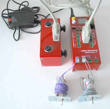
7 – Action – Turning off the MotorVator®. The instructions are on page 14 of the ring bound Manual and are repeated below.
Press the Red Off button to stop any program running. Again press and hold down the Red Off button for at least two seconds, a tune will play and the two character LCD display will go out. The transformer can then be unplugged from both MotorVator® and the 240 volt socket.
8 – Suggestions – (a) - Make a temporary removable sticky paper label to go around the left side toggle lever and mark the label to show what the eight positions do.
(b) – Use a permanent maker pen and write your surname (small) on every piece of equipment, cable, motors and packing box. Everybody’s MotorVator® equipment looks the same .