- Home
- Products
- Articles
- 4 Axis Robot Arm
- A Stepper Motor Driven Ferris Wheel (Version 3 Compiler required)
- An Update on Keith Cameron's Lift
- Automatic Tram Layout
- Bug in Increment Word Instruction
- Compiler Version Releases
- Industrial Arc Welding Robot
- MotorVating the Speed Play Robot
- Reproducing the Electronic Set Models
- Sensor Expansion Port Pinout Diagram
- Sheet 1 - Hardware from NZ 240 volt wall socket to...
- Sheet 3 Meccano Car model controlled by the MotorVator and Director.
- Sheet 2 - Hardware from Motor(s) to MotorVator®.
- User Input Options
- Version 3 Manual Released
- 16/32 Bit Maths Routines
- Build Your Own Photo Sensor
- Controlling Stepper Motors
- Magnetic reed switch as a non contact sensor
- MeccCompiler III Tutorial
- More Inputs and/or Motors: Port Replication
- More Inputs: the Sensor Expansion Port
- Square Root Function
- Tutorial: Rev Counter
- Use of the opto switch or opto interrupter as a ro...
- FAQ
More Inputs and/or Motors: Port Replication
The MotorVator supports 8 inputs (4 x OnOff, 2 x Timed and 2 x Analogue) and 4 motor outputs in the basic configuration.
We are often asked how one could support more motors.
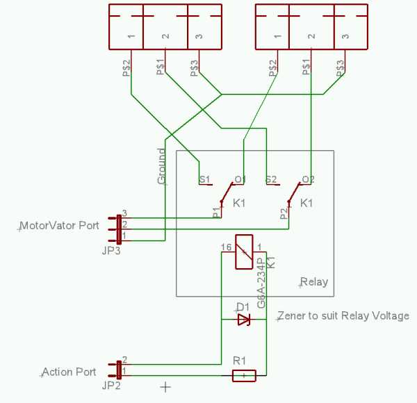
Using a simple DPDT relay, controlled by one of the Action Output ports, you can easily "multiplex" any port (input or output) into two.....

NOTE if You are going to wire up your own relay, DO NOT SHORT the Action Outputs - you will BLOW the MotorVator Action Port Transistor
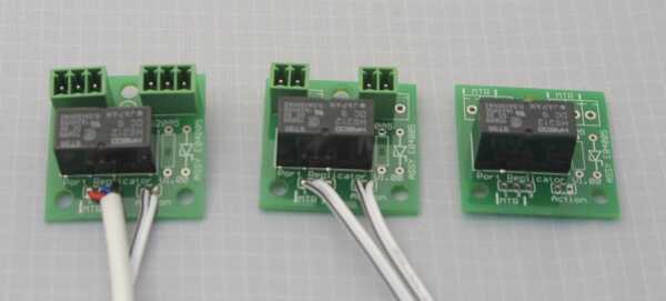
For those who don't want to build their own relay board, we've developed a simple Printed Circuit Board, with three different options.

From left to Right
Port Replicator 3 - fully assembled, turn any port (2 or 3 way) into two.
Port Replicator 2 - fully assembled, replicate motor ports and OnOff Input ports.
Port Replicator Kit - includes PCB, relay and Motorvator plugs. Assemble yourself using solder connections for your inputs. Includes 2 way plug for Action Output, and 2 and 3 way plug for Motorvator port.
Mounting holes match Meccano geometry.
NOTE Take Special care in wiring to the Action Output - you must connect the Left of the two Action Wires (as viewed in the above photo) to the Right Hand Action Port connector (when viewed from the Motor End of the MotorVator
To use, connect to one of the Action Ports, then use the SetAction statement, e.g.
SetAction     1,0          ; turn relay, so Motor A = Motor 1

	SetMotor      1,F,50     ; start motor 1

	Wait 500                    ; wait for 5 seconds

	SetMotor      1,F,0       ; stop motor 1

	SetAction     1,1         ; turn relay on, so Motor A = Motor '5'
SetMotor      1,F,60     ; start motor '5'
etc
You can buy these at MeccParts.com Meccanisms Accessories
