- Home
- Products
- Articles
- 4 Axis Robot Arm
- A Stepper Motor Driven Ferris Wheel (Version 3 Compiler required)
- An Update on Keith Cameron's Lift
- Automatic Tram Layout
- Bug in Increment Word Instruction
- Compiler Version Releases
- Industrial Arc Welding Robot
- MotorVating the Speed Play Robot
- Reproducing the Electronic Set Models
- Sensor Expansion Port Pinout Diagram
- Sheet 1 - Hardware from NZ 240 volt wall socket to...
- Sheet 3 Meccano Car model controlled by the MotorVator and Director.
- Sheet 2 - Hardware from Motor(s) to MotorVator®.
- User Input Options
- Version 3 Manual Released
- 16/32 Bit Maths Routines
- Build Your Own Photo Sensor
- Controlling Stepper Motors
- Magnetic reed switch as a non contact sensor
- MeccCompiler III Tutorial
- More Inputs and/or Motors: Port Replication
- More Inputs: the Sensor Expansion Port
- Square Root Function
- Tutorial: Rev Counter
- Use of the opto switch or opto interrupter as a ro...
- FAQ
Build Your Own Photo Sensor
In the 1970s, Meccano marketed an Electronics Set:
This set allowed a number of "automated" models to be built. All relied on input from the PhotoCell. I thought it would be an interesting exercise to build some of the models, using the MotorVator in place of the Meccano Relay Box.
However, the first thing I need is a PhotoCell........
The Meccano photocell uses a Cadmium Sulphide PhotoCell, now more commonly called a Light Dependent Resistor (LDR). An LDR changes its resistance depending on the light falling on it. So we can connect an LDR to a MotorVator Analogue Input and measure the changes, as follows:
LDRs are readily available from hobby electronics shops. The value of the Resistor should roughly match the "Dark Resistance" of the LDR.
It is helpful to have the sensor shielded from ambient light, so I assembled the components into a #163 Sleeve Piece......
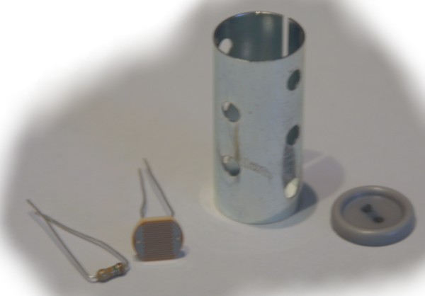
Find a button of suitable diameter to be a neat fit inside the sleeve (colour not important), drill to take the LDR leads, then solder the connections behind the button.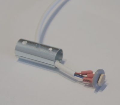
Route the wires out of the side hole and slide the assembly into the Sleeve. Secure with silicon or similar.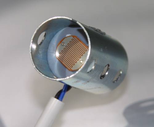
Fit a sleeve of dark paper inside the sleeve.
To use the sensor, simply connect to an analogue port and read the value. e.g.
declare constant threshold = 60  ; for example
declare byte light

	loop
	light = readanalogue(1)
displayhex light                  ; display what the reading is for testing purposes
if light > threshold then       ; reading goes up when dark

	       call do_whatever

	end if
	end loop
You'll need to work out a suitable threshold value for your light source and ambient light. Given that ambient light changes, to avoid having to make changes in your program I'd suggest using another Analogue Input with a simple potentiometer, to set your threshold. A 10K ohm potentiometer should work fine. This way you can adjust it while the program is running, to get the trigger point that you want.
;

	; Use the Photo Sensor to display ST for STOP when dark (i.e. blocked)

	; and GO for GO when open
;
begin program
	Declare Byte threshold
Declare Byte light

	Loop
	light = ReadAnalogue(1)
threshold = ReadAnalogue(2) ; get the threshold
If light > threshold Then       ; reading goes up when dark

	     DisplayChars "S","T"
	Else

	       DisplayChars "G","O"
	End If
	End loop
	End Program
For the light source, I suggest using the head assembly from a small torch.